What Is a Pressure Pump and How Does It Work?
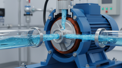
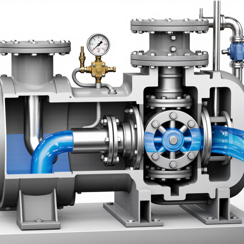
A pressure pump is more than a motor pushing water through a pipe. It is a carefully matched system that creates flow, maintains pressure, and overcomes resistance. Inside the casing, an impeller, piston, diaphragm, or rotary element transfers mechanical energy into the fluid. The result may be a strong spray, steady building supply, or precise industrial flow.
Igor J. Karassik, a respected pump engineer and editor of the Pump Handbook, described the pump as “the heart of the system.” That image is useful. A pressure pump must work with pipes, valves, filters, tanks, and the final outlet. If one part is poorly sized, pressure can fall, noise can rise, or the motor may work harder than expected. Small details matter.
The working process is straightforward. The pump draws fluid through an inlet, increases its pressure, and sends it toward a discharge line. Sensors or pressure switches may control starting and stopping. Yet real performance depends on fluid temperature, viscosity, elevation, pipe length, and maintenance. A pump that performs well in a clean test tank may struggle with sediment or air in the line.
That is where careful selection becomes important. Not every high-pressure model suits every application. Flow rate matters. So does pressure stability. This guide explains the main pressure pump types, their internal action, practical uses, and common warning signs. It will not pretend every installation is simple. Field conditions often expose assumptions that look reasonable on paper.
What Is a Pressure Pump?
What Is a Pressure Pump?
A pressure pump is a mechanical device that increases water or fluid pressure. It does not create fluid from nothing. Instead, an impeller, piston, or diaphragm transfers energy to fluid moving through a system. The pump helps overcome pipe friction, elevation changes, and demand from outlets. In a home, it may support showers, taps, or irrigation. In industry, it can serve boilers, cooling circuits, and process lines.
The operating cycle is straightforward. An electric motor or engine drives the pumping element. Fluid enters through the suction side, gains velocity and pressure, then leaves through the discharge line. A pressure sensor can start or stop the motor as demand changes. A control tank reduces frequent cycling. A practical field check matters: blocked filters, undersized pipes, and air leaks can reduce performance, even when the pump appears powerful.
A useful caution: more pressure is not always better. Excess pressure can damage seals, joints, valves, and appliances. The U.S. Department of Energy reports that pumping systems may consume about 25% of electricity in some industrial facilities. Correct sizing therefore affects both reliability and operating cost. The WHO and UNICEF Joint Monitoring Programme reported that 2.2 billion people lacked safely managed drinking water in 2022, showing why dependable pumping remains important. The definition sounds simple. Real systems are messier.
What Is a Pressure Pump and How Does It Work?
A pressure pump increases the pressure of a fluid by converting mechanical energy from a motor into hydraulic energy. The chart shows representative operating-pressure ranges for common pressure-pump applications. Actual pressure depends on system design, flow rate, elevation, pipe resistance, and safety requirements.
How it works: Fluid enters through the suction side, the impeller or piston transfers energy to the fluid, and the pressurized fluid leaves through the discharge side. A pressure switch, controller, or variable-speed drive may regulate the output.
How a Pressure Pump Works Step by Step
What Is a Pressure Pump and How Does It Work?
How a Pressure Pump Works Step by Step
A pressure pump raises fluid pressure when gravity or existing supply pressure cannot meet demand. In practical installations, the process begins at the inlet. A motor turns the pump shaft, while an impeller, piston, or diaphragm moves the fluid into a confined chamber. The moving component transfers mechanical energy into pressure and flow.
The next step controls direction. An inlet valve opens as pressure falls inside the chamber. Fluid enters through the suction pipe. The valve closes when the chamber fills. A discharge valve then opens as internal pressure rises. Pressurized fluid travels through the outlet pipe. A pressure switch may stop the motor when the system reaches its set point.
It sounds simple. Real systems are less tidy.
Pipe friction, air leaks, blocked filters, and incorrect sizing can reduce performance. I have seen a pump run continuously because a small leak prevented pressure recovery. That fault increased heat and energy use. The U.S. Department of Energy identifies pumping systems as significant industrial motor-energy users, making efficiency checks worthwhile. The International Energy Agency also reports that electric motor systems consume more than half of global electricity, reinforcing the value of correct pump selection.
Pressure gauges should be checked during startup and under normal flow. Manufacturers and engineers commonly compare pressure, flow rate, motor load, and cycling frequency. A rising noise level may indicate cavitation, not higher performance. That detail is easy to miss.
Main Components and Their Functions
What Is a Pressure Pump and How Does It Work?
A pressure pump increases water pressure when gravity or municipal supply cannot meet demand. Its main components work as one controlled system. The electric motor provides rotation, while the impeller transfers energy to the water. In positive-displacement designs, pistons or diaphragms move water through repeated chambers.
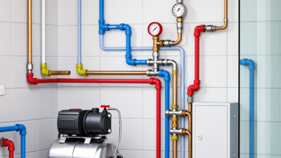
A pressure switch or electronic sensor monitors outlet pressure. When pressure falls, it starts the motor. A check valve prevents reverse flow after shutdown. The pressure tank stores a small water reserve and reduces frequent starts. A relief valve protects the casing and pipework from excessive pressure. Gauges reveal pressure changes, although a dirty gauge can mislead technicians.
Small parts matter.
An inlet filter keeps sand away from the impeller. Poor filtration can cause vibration, noise, and early wear. The U.S. Department of Energy’s Pumping System Assessment Tool literature indicates that pumping systems may consume 25–50% of electricity in some industrial facilities. Correct sizing therefore affects both pressure and operating cost. Oversizing is not automatically safer.
In practical maintenance, I would check leaks, cycling frequency, and motor temperature before adjusting controls. A pump that starts every few seconds may have a failed tank bladder or hidden leak. Hydraulic Institute guidance also emphasizes matching pump duty to the system curve, not simply choosing the highest pressure rating. This distinction is easy to miss. Real installations are rarely perfect. Pipe friction, elevation, and changing demand can make textbook calculations incomplete.
Common Uses and Operating Considerations
What Is a Pressure Pump and How Does It Work?
A pressure pump moves liquid by converting motor energy into controlled fluid pressure. An impeller, piston, or diaphragm creates movement inside the pump chamber. The inlet draws liquid in, while the outlet pushes it through pipes at higher pressure. A pressure switch or electronic controller may adjust operation when demand changes.
Common uses include boosting water flow in tall buildings, supplying irrigation lines, feeding boilers, and supporting cleaning equipment. In a workshop, a pump can maintain steady pressure while several outlets operate. Household systems often use pressure tanks to reduce frequent starts. The actual result depends on pipe length, elevation, fittings, and flow demand. A pump that looks powerful on paper may still deliver weak pressure.
Operating conditions deserve close attention. The pump must receive enough liquid and should never run dry. Low inlet pressure can cause cavitation, producing a harsh rattling sound and damaging internal parts. Clean filters help, but overly fine filters can restrict flow. Check the liquid temperature, viscosity, and chemical compatibility before selecting materials. Install a relief device where blocked discharge could create dangerous pressure. Regularly inspect seals, connections, vibration, and unusual noise. Small leaks often become expensive failures. That assumption deserves checking.