
Choosing a Fuel Pump Motor Commutator is not just a matter of matching its outside diameter. The commutator must suit the motor’s design, operating current, rotational speed, and brush system. A mismatch can cause uneven brush wear, excess heat, or unstable electrical contact. Small details matter.
Start with the motor’s service data, then check the commutator’s diameter, bar count, shaft fit, and overall length. Inspect the copper surface for smooth, even bars, and look closely at the mica insulation between them. Deep grooves, lifted bars, or uneven wear may point to problems beyond the commutator itself. Fit comes first. A replacement that looks similar may still have the wrong dimensions or electrical characteristics.
Material and manufacturing quality also deserve careful attention. Ask for documented specifications and verify that the part is intended for the particular motor model and its operating conditions. Brush compatibility matters, too; the wrong grade can wear quickly or leave damaging debris. In a compact pump motor, heat and vibration make small defects harder to ignore. Not every failure starts at the commutator.
This guide explains how to compare key specifications, assess visible condition, and avoid common selection mistakes. Where measurements or application details are uncertain, confirm them with the motor manufacturer or a qualified supplier rather than relying on appearance alone. That extra check can save time, though it may not reveal every underlying fault. A careful choice begins with evidence.
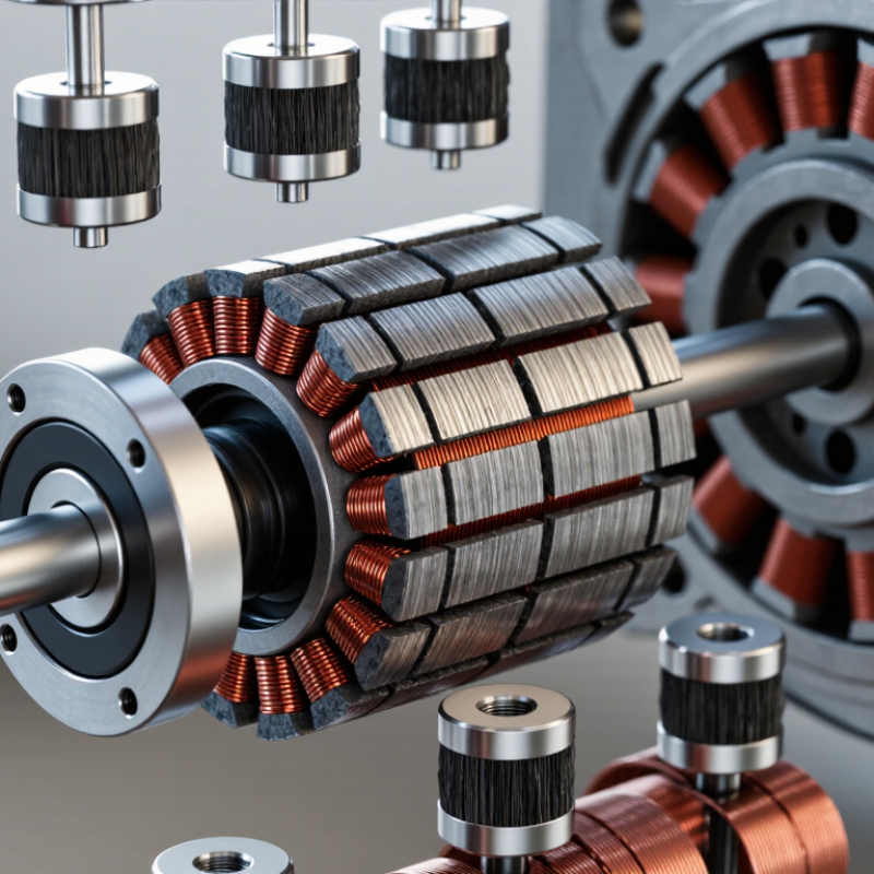
Inside a typical brushed fuel pump motor, the commutator is a segmented copper ring attached to the rotating armature. Carbon brushes press against its surface. As the armature turns, the segments switch current through the windings, helping maintain useful torque. That contact matters. Without it, electrical energy cannot reach the rotating coils in the right sequence.
A clean, even commutator helps the motor run steadily. Each segment passes under a brush repeatedly, so small defects can have ongoing effects. Grooves, burnt spots, loose segments, or heavy carbon deposits may interrupt current flow. The pump may sound uneven, draw inconsistent current, or fail to reach expected pressure. These signs do not prove the commutator is damaged; wiring, brushes, a clogged filter, or a worn pump can cause similar symptoms. Small parts, big effect.
When inspecting a motor, check for even copper surfaces and firm segment edges, along with brush length and spring pressure. A dark mark alone can mislead; some discoloration is normal after use. Appearance is not enough. Electrical continuity and measured pump output offer a more reliable assessment. Service options also depend on the motor design, since many sealed fuel-pump assemblies are replaced as complete units rather than repaired internally.
How to Choose a Fuel Pump Motor Commutator
Which Operating Conditions Shape Commutator Selection
Fuel pump commutator selection begins with the conditions inside the motor, not a catalog label. In many in-tank designs, fuel cools and lubricates components while contacting insulation and nearby materials. That makes fluid compatibility essential. Temperature swings, low supply voltage, frequent starts, and long high-load runs all change electrical and thermal stress. Map the full duty cycle.
Match commutator geometry and copper grade to current density, brush pressure, and expected speed. High current can increase arcing and local heat; poor runout or rough surfaces can accelerate brush wear. Small defects matter. Fuel cleanliness and vibration deserve attention too, since particles and movement can disturb consistent brush contact. Insulation systems and joining methods should remain stable across the specified fuel and temperature range.
Ask for evidence from tests that resemble service: hot and cold starts, voltage dips, vibration, and repeated cycling. Measure wear, electrical noise, temperature, and performance drift over time. A bench result helps, but it is not the whole story. I would not treat one clean test as proof. Real fuel, heat, and aging can expose weak assumptions.
Fuel pump motor commutators differ in both material and construction. Many use copper segments because copper conducts current efficiently, but the grade and hardness can vary. A harder material may resist wear, while conductivity and heat behavior still matter. Small details matter. The segments are separated by thin insulation, often mica or a similar material, which prevents unwanted electrical contact as the motor turns.
Design changes affect how brushes meet the commutator. Segment width, spacing, surface finish, and commutator diameter can influence contact stability and heat buildup. A compact design must handle repeated starts and changing electrical loads inside a confined pump housing. Brush material matters too; it needs to work with the commutator rather than wear it quickly. There is no single layout that suits every motor.
When comparing replacement parts, match the commutator to the motor’s dimensions and operating requirements, not appearance alone. A bright copper surface is not proof of good quality. Check segment alignment, insulation condition, and the specified fit. I would be cautious about judging a worn part from color alone; residue and lighting can mislead. Measurements and manufacturer specifications offer firmer evidence, though older assemblies may not provide much documentation.
| Selection Dimension | Common Option | Typical Characteristics | When to Consider It | Checks Before Selection |
|---|---|---|---|---|
| Segment material | High-conductivity copper | Provides a conductive brush-contact surface and is widely used in small DC motor commutators. Performance depends on copper grade, manufacturing quality, and operating conditions. | A general-purpose starting point when electrical losses and brush contact are primary concerns. | Confirm current demand, commutator temperature, brush type, and the motor maker’s material specification. |
| Heat resistance | Heat-resistant copper grade, where specified | Some copper grades or alloy additions can improve resistance to softening at elevated temperatures, but may affect conductivity and cost. The benefit is grade- and process-dependent. | Potentially useful when testing shows high commutator temperatures or thermal distortion. | Compare verified temperature capability and conductivity; do not infer suitability from a material name alone. |
| Segment insulation | Mica between copper segments | Separates adjacent segments electrically and must retain its integrity under heat, vibration, and centrifugal loading. Segment spacing and insulation condition affect reliable commutation. | A key consideration for conventional segmented commutators operating through repeated start-stop cycles. | Check insulation condition, segment alignment, and the specified undercut or flush finish. |
| Commutator construction | Segmented cylindrical commutator | Copper bars are arranged around the armature shaft and insulated from one another. Bar count, diameter, and connection layout are designed for the motor winding and operating speed. | Common in brushed DC motors; choose a construction matching the original armature and motor design. | Match dimensions, segment count, runout, shaft fit, and winding connection layout. |
| Brush connection style | Riser, hook, or slot connection, depending on design | The connection feature links armature winding wires to the commutator segments. These styles are not interchangeable without matching the winding and assembly method. | Select according to the existing armature construction and manufacturing requirements. | Verify lead routing, joint integrity, clearances, and resistance to vibration. |
| Mica finish | Undercut or flush, as specified | Undercutting recesses the mica below the copper surface; a flush design keeps the surfaces closer to level. The appropriate finish depends on commutator design and brush behavior. | Use the finish specified for the motor rather than assuming one style is universally better. | Check for burrs, uneven segment height, and mica protrusion that could interfere with brush contact. |
| Brush compatibility | Brush grade matched to commutator surface and duty | Brush material, contact pressure, current density, and surface finish influence wear, heating, and sparking. A commutator change can alter performance if the brush system is not considered as a pair. | Always consider the commutator and brushes together, especially when changing material or finish. | Review brush grade, spring force, contact area, and observed wear or arcing during testing. |
| Fuel-pump operating environment | Application-specific motor and pump assembly | The commutator operates inside the motor. Fuel exposure, cooling, sealing, and electrical insulation depend on the pump architecture; copper selection alone does not establish fuel compatibility or safety. | Evaluate the complete motor-pump system for its intended fuel, temperature range, and operating duty. | Use qualified application testing and verify the complete assembly’s material and electrical requirements. |
Check the commutator’s bore, outside diameter, stack width, and shaft shoulder against the motor drawing. A close-looking fit is not proof.
ISO 286-1:2010 lists an IT6 tolerance of 9 micrometres for nominal sizes over 6 mm through 10 mm. That figure describes a tolerance grade, not an automatic fit recommendation; use the drawing’s specified limits.
Also check shaft runout and commutator concentricity with a dial indicator. Small errors matter. A slight wobble can make the brushes ride unevenly, leaving a narrow, patchy contact track.
Next, inspect the brush assembly with the commutator installed. Confirm that each brush moves freely in its holder and meets the copper surface squarely. Check spring pressure against the motor maker’s specification, then look for binding, chipped edges, or uneven wear.
ASTM B193-20 gives a test method for electrical resistivity; its 100% IACS reference corresponds to 58 MS/m at 20°C. This is useful material context, not a pass/fail value for every commutator alloy.
Fit is mechanical, but contact is electrical too.
A detail that is easy to miss: the correct diameter can still produce poor brush seating if the commutator face is out of round. Measure, inspect, and compare the readings with the motor specification before assembly.
Durability starts with the commutator’s surface and geometry. Look for pitting, raised copper, uneven wear, and dark heat marks around the bars. A smooth appearance helps, but it proves little on its own. Measure runout and bar-to-bar resistance with suitable instruments, then compare results with the motor’s specified limits. Record readings before and after endurance testing; small changes can reveal wear that a quick visual check misses.
Confirm performance under representative load, not only on an unloaded bench. Monitor current, speed, and temperature while the motor runs, then repeat the test after vibration and thermal cycling. Watch for unstable current, slowing rotation, or brush chatter. Keep test conditions consistent, including supply voltage and operating temperature.
This matters.
A short test can hide developing faults. A longer test may still miss wear caused by real-world contamination or start-stop cycles. That is the imperfect part. Combine electrical readings with a close inspection of brush contact and commutator wear. If results vary between repeated runs, investigate the setup before judging the component. Use application-specific acceptance limits; universal numbers can mislead.
sale@harbertpump.com,
sale@harbertpump.com